Symbol Pane
Introduction
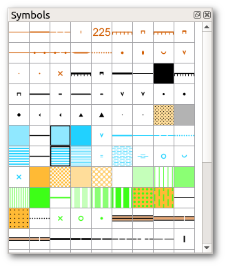
The symbol pane shows all symbols in the opened map file arranged in a grid. Hovering the cursor above a symbol shows its name and its number, which comes from the respective orienteering symbol set standard. Pressing F1 while hovering over a symbol shows the detailed description from the standard document for this symbol, if available.
Symbols in this view can be selected like in a file manager:
- Clicking a symbol selects it exclusively.
- Clicking a symbol while holding Shift toggles the selection of all symbols between this one and the previously selected symbol.
- Clicking a symbol while holding Ctrl toggles the selection of this symbol only
Right clicking shows the symbol menu.
Symbol types
Point symbols are features with small extent, so point objects are represented by a single coordinate. Examples are single trees or small knolls.
Line symbols depict linear objects such as paths or small watercourses. Line symbols can contain point symbols: the fence symbol for example represents its dashes by a point symbol.
Area symbols depict objects with a larger extent which is shown on the map in plan shape, for example buildings or thickets. They can be filled with a solid color, or with different kinds of line and dot patterns.
Text symbols contain font settings such as size, color or thickness. They are used to standardize the appearance of texts on the map, like control numbers or spot heights, but are also used for titles, legends and other notes. Text size may be approximated as 0.24 times the point size for a typical easy to read font (but some fonts may depart significantly from this rule of thumb). Thus 6pt font has a letter height of 6*0.24=1.44 mm. Choosing an uncommon font may create problems for others opening the map on computer systems where this font is not installed, as font files are not embedded in map files.
Combined symbols are made up of two or more other line or area symbols. This is for example used to combine the gray fill and black outline for houses in sprint maps into a single symbol.
Symbol menu
To show the symbol menu, right click the symbol pane:
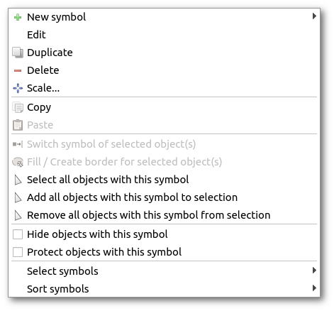
- The actions in the first section enable to create new symbols or edit the selected symbol.
- The actions in the second section enable to copy/paste symbols.
- In the third section, in addition to the possibility to select all symbols with the selected object, there are shortcuts to the two drawing functions switch symbol and fill / create border.
- The fourth section enables to hide all objects with a given symbol, for example to remove all paths from a map, and to protect all objects with a given symbol from editing. This is useful to make large area symbols static while editing other objects on top of them.
- The last section offers actions for symbol selection and sorting.
Symbol editor
Introduction
The symbol editor enables to create new symbols or to modify any of the existing symbols. Its main use in normal operations is to create symbols for map labeling, because no symbols for this purpose are provided by default as they depend on the desired styling of the map sheet. Regarding symbols for use in the map itself, it should be understood that the default symbol sets include all the symbols permitted by the ISOM or ISSprOM and that any new symbols created, or modifications of existing symbols, will be a departure from the international standard.
There is a temptation to employ a symbol which is used in other local cartography to represent some feature on the basis that everybody who competes in this area is familiar with the notation. However, any such departure is confusing for a competitor who may be familiar with the international standard but not with your local notation. Similarly a local competitor may find the conforming notation strange when entering international competition. Thus a non-standard notation can be to the disadvantage of both local and visiting competitors.
The symbol editor is opened from the symbol menu which is triggered with a right-click on any symbol. The menu offers options to create a new symbol or to edit the selected symbol.
In each case the dialog opens with a General page which offers common options for all symbol types, which is followed by pages specific to each type of symbol. On the right is a preview of the symbol as it is currently configured, in a variety of lengths and orientations. This preview can be moved and zoomed with the middle mouse button and mouse wheel.
General page
At the top, the symbol number and name can be entered. Both are specified in the ISOM and ISSprOM for orienteering symbol sets. It is recommended that helper symbols are given numbers in the third subset (which is not used by ISOM). Thus a helper for symbol number x.y might be numbered x.y.1.
The description text appears when pressing F1 while hovering over the symbol with the cursor. For orienteering symbol sets, it is directly taken from the ISOM and ISSprOM documents.
At the foot of the dialog is a box which when checked hides the symbol when the map is printed out. It is intended for helper symbols which mark certain terrain features which are useful for mapping but will not be represented in the final map. Use this with care! When accidentally ticked, symbols will disappear in printouts without further notice!
Line settings
Line width and color define the basic line characteristics. Minimum line length function is not yet implemented. Line cap permits the shape of the end of the line to be specified. Line join refers to the rendering of vertices where line sections of different orientations join each other.
Dashed lines are created by a tick in the dash box, which shows the dash dialog settings. Typical length of dash and gap may be specified; these will be rendered with gaps of the specified size and dashes as close as practicable to the specified length (so that there is no fractional dash at the end). The appearance of lines with regular symbols or breaks may be improved by making the end dash a half length; a check box provides for this. Dashes may be grouped together with a specified gap within the groups which is different from the between-group gap length.
Many symbols (e.g. 513 Wall) have a repeated feature along the line. This line feature is invoked by setting a non-zero integer number in the mid-symbol count. The mid-symbol distance sets the spacing between symbol centers. The distance between spots refers to the distance between symbol groups; if the mid-symbol distance is too large then the groups may overlap. The distance from the end is an approximate length of line projecting beyond the last group. A check box to require at least one mid-symbol ensures that the line has at least one symbol but may give confusing results if the line is too short for meaningful rendering. Setting a minimum mid-symbol count is not yet implemented. A different mid-symbol minimum may be specified for the boundary line of a closed symbol.
Some line symbols require an outline which is enabled by selecting the border check box. Border width is the width (thickness) of the border lines. Shift moves the border lines further apart; shift equal to half the border width will place the line just outside the edge of the main line. A dash feature with characteristics which do not have to match the main line is enabled by the corresponding check box.
Start symbol
The start symbol will appear only at the first-fixed end of the line. This can be changed for a particular line with the switch dashes / reversing tool. The start is the left end of the horizontal sample lines in the illustrative graphic to the right of the symbol editor. The start symbol may be made of several elements. To add an element click the + button at the bottom of the elements list. To delete one click the - button. An element may be a point (a circular element), a line or an area element.
The default feature is a point element (line or area elements must be added). Point elements have inner diameter and outer width which may be different colors, and will be centered on the beginning of the main line.
A line element has width, color, end-shape and join characteristics specified in the current element dialog. The line may have any shape defined by successive pairs of coordinates, add more coordinate pairs with the + button at the bottom of the coordinates window and delete them with the - button. Another way to add a coordinate is to left click the desired position in the preview at the right. A right click repositions the currently selected coordinate. The coordinate system origin is the beginning point of the symbol line, the X axis is positive in the direction of the main symbol line, and the Y axis is up the screen. Curved lines are created by constructing a shape with straights first and then clicking the “Curve start” check boxes to make some parts curves. Better results may be obtained with curves which do not bend more than 90 degrees.
An area element has a color and a shape specified in the current element dialog. The shape of the area is defined just as for lines, see above.
Mid symbol
These symbols appear along the line at the spacing set for mid-symbols in the ‘line settings’ dialog. Mid symbols are edited like start symbols (see above).
End symbol
This symbol appears only at the last-fixed end of the symbol line. This can be changed for a particular line with the switch dashes / reversing tool. The end symbol will appear at the right end of the of the horizontal sample lines in the illustrative graphic to the right of the symbol editor. End symbols are edited like start symbols (see above).
Dash symbol
This symbol will appear at dash points along a line; drawing these can be toggled by pressing the space-bar while the drawing tool is active. The symbol will appear at each node drawn while the helpful tip at the bottom edge shows “Dash points on.” This switch may vary from point to point along the line. Dash symbols are edited like start symbols (see above).